The Top Mount is the structure on which the wire is fixed, where the magnet and the Hall sensors sit and where some adjustments can be done.
The top mount must be fixed very ridgidly to the structure of the building.
In the early days of my experiments I have used a number of alternatives which simply did not work or did not last long enough.
Overview
Cable clamp
Magnet mount
Hall PCB
Overview
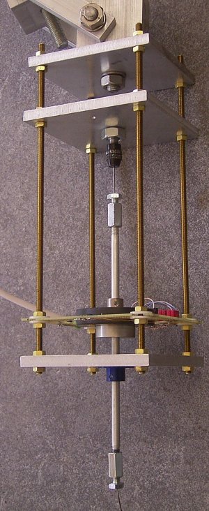
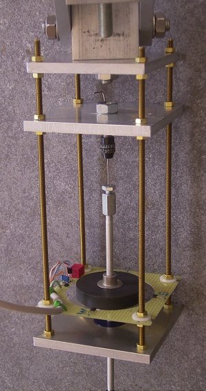
Fig 1. Fig 2.
The Top plate allows vertical fine-adjusting the assembly below it in East-West and in North-South direction, and it can be rotated to point North. See Adjustments.
The second plate carries the Proxxon Clamp which holds the wire. You may sharply bend the wire above it to prevent slipping out.
Then we have the PCB with the Hall sensors.
The bottom plate keeps things together and has a hole in which the blue collar fits tightly for a calibration purpose.
Threaded rods and nuts are brass.
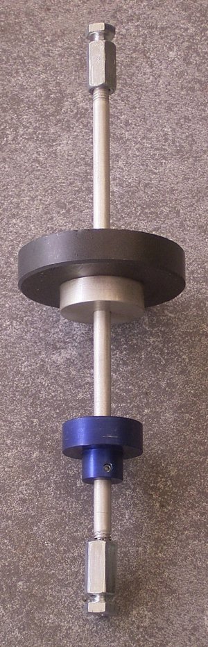
Fig 3. Magnet carrier.
The black part is the magnet, harvested from a defect loudspeaker. But nice magnets are for sale in many metal shops. Find one with a through hole, do not try to drill a hole in a magnet yourself, it is almost unmachinable material.
The blue collar fits tightly in the hole of the lower plate for calibration purposes. Normally it sits low so that it does not touch anything.
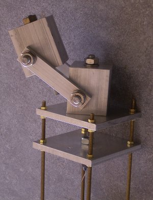
Fig 4. Ridgid Mount.
This is one of the ways to mount your pendulum ridgidly to a structure in the building. It allows rotation in the horizontal plane to precisely adjust it in the North - South direction. Fine adjustment of verticality is done with the nuts on the upper plate. See Adjustments.
Cable clamp
The cable clamp is made from a piece of M10 threaded rod and spare parts for a Proxxon PCB drilling machine. .
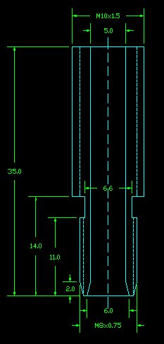
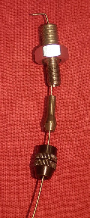
Fig 5. Drawing Fig 6. Proxxon Mount.
The proxxon cap has threading M8x0.75, which is not standard. I was able to cut the threading with my lathe.
Magnet mount
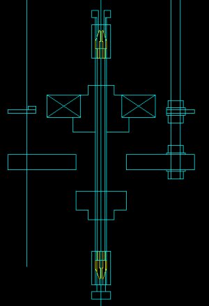
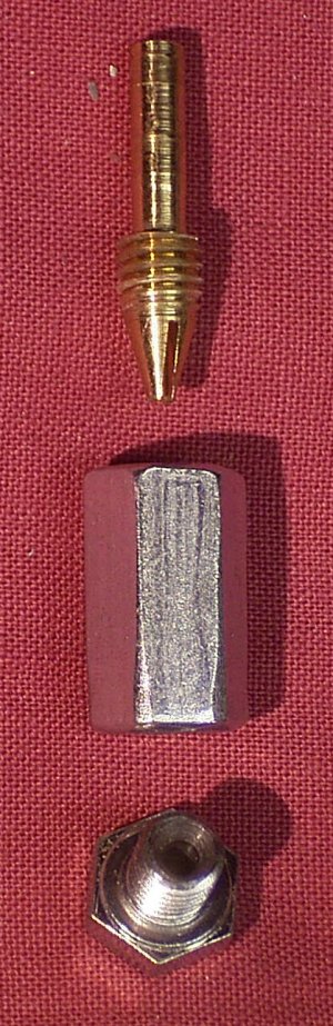
Fig 7. Magnet mount. Fig 8. Magnet Clamp.
Also see fig 3.
The wire is clamped on both ends of an aluminium tube of 6mm outer diameter with brass nose pieces and modified M6 bolts sitting in a long M6 coupling nut. The aluminium tube is threaded M6 on both ends.
The manufacturing of the noses is not evident, so I give the order of working on the lathe.
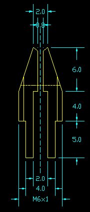
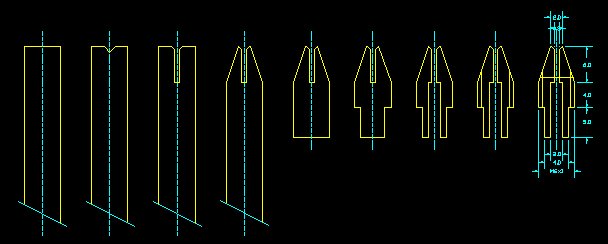
Fig 9. Drawing of nose Fig 10. Order of working.
1/ Start with a brass rod of 6 mm diameter and flatten the face.
2/ Drill a very shallow centerpit with a centerdrill.
3/ Drill the hole of (in my case) 1mm diam.
4/ Taper the end.
5/ Cut it off slightly longer than required with a handsaw.
6/ Flatten the other face.
7/ Bring to the required diameter to fit tightly into the aluminium tube.
8/ Center, and drill the larger hole.
9/ Cut M6 threading on it.
10/ Cut the slit in the nose.
For 6, 7, 8 the piece has to be clamped in the lathe with the nose pointing inwards. for 9 and 10 it has to be clamped on the diameter which fits into the aluminium rod.
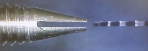
Fig 11.
Slit cutting with a 0.5 mm thick circular saw. Image from the USB microscope.
Do not use a diamond saw, it wil produce a much wider slit.
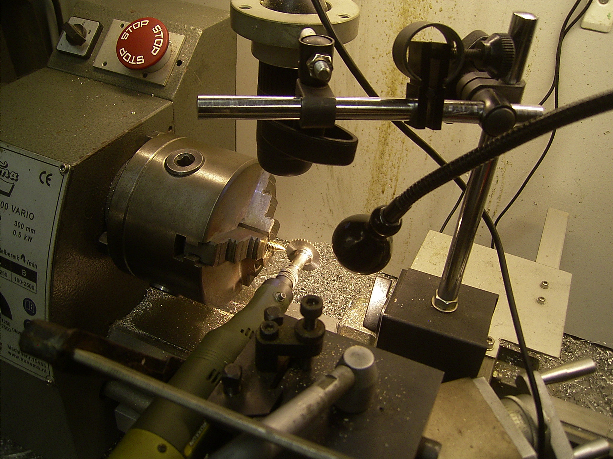
Fig 12. Slit cutting setup
The 0.5 mm thick saw was mounted on the Proxxon machine, clamped to the lathe support.
To accurately position the saw I used a USB microscope looking downward.
Hall PCB
The Hall PCB contains the 4 Hall sensors and a temperature sensor.
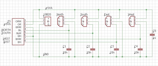
Fig 13. Schema of the Hall PCB.
The position of the Hall sensors is quite critical. The temperature sensor appears to have non-magnetic wires. I managed to find non magnetic capacitors too. You might know that many electronic components have ferromagnetic wires. In the vicinity of the magnet and the sensors it is probably wise to avoid that.
I did not use a RJ45 connector here, I just soldered the cable to the board. Do have a good tensile relief.
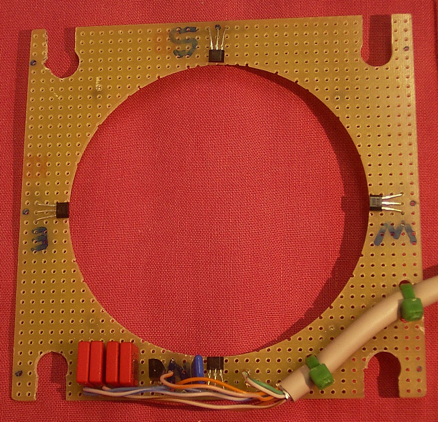
Fig 14.
Top side of the board.
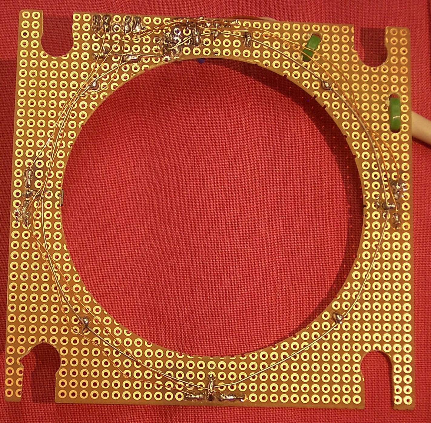
Fig 15. Bottom side with hand wiring.